Generator Schematic Symbol : Generator Schematic Symbol | Wiring Diagram Database / They are also known as circuit symbols or schematic symbols as they are used in electrical schematics and diagrams.
Generator Schematic Symbol : Generator Schematic Symbol | Wiring Diagram Database / They are also known as circuit symbols or schematic symbols as they are used in electrical schematics and diagrams.. Fuse symbol represents the fuse that protects the circuit from over current. Xor gate (sometimes eor, or exor and pronounced as exclusive or) is a digital logic gate that gives a true (1 or high) output when the number of true inputs is odd. Figure 2, shows a cross sectional schematic for rectangular tube photovoltaic thermal collector and detail specification of system is shown in table 6. That is, a true output results if one, and only one, of the inputs to the gate is true. Crystal oscillator used to generate clock signal of very precise frequency.
That is, a true output results if one, and only one, of the inputs to the gate is true. (ul = ut + ub) ii. They are mostly used to draw a circuit diagram and are standardized internationally by the ieee standard (ieee std 315) and the british standard (bs 3939). An xor gate implements an exclusive or (↮) from mathematical logic; Crystal oscillator used to generate clock signal of very precise frequency.
Electric Generator Symbols from www.electrical-symbols.com Xor gate (sometimes eor, or exor and pronounced as exclusive or) is a digital logic gate that gives a true (1 or high) output when the number of true inputs is odd. In electronic circuits, there are many electronic symbols that are used to represent or identify a basic electronic or electrical device. Mar 19, 2021 · the symbol represents the light bulb. They are mostly used to draw a circuit diagram and are standardized internationally by the ieee standard (ieee std 315) and the british standard (bs 3939). Fuse symbol represents the fuse that protects the circuit from over current. Rectangular tube collector if number of glass cover was double, determine: ( 15 marks, c4) w=0.05m dis 0.017 figure 2: The bulb glows when required voltage is applied.
(ul = ut + ub) ii.
The bulb glows when required voltage is applied. An xor gate implements an exclusive or (↮) from mathematical logic; Motor this converts the electric energy to mechanical energy. Basic electrical and electronic graphical symbols called schematic symbols are commonly used within circuit diagrams, schematics and computer aided drawing packages to identify the position of individual components and elements within a circuit. Crystal oscillator used to generate clock signal of very precise frequency. Xor gate (sometimes eor, or exor and pronounced as exclusive or) is a digital logic gate that gives a true (1 or high) output when the number of true inputs is odd. In electronic circuits, there are many electronic symbols that are used to represent or identify a basic electronic or electrical device. Feb 24, 2012 · an electrical symbol is a small image used to represent an electrical or electronic device or function. There are six pins from the set of digital pins that are pwm (pulse width modulation) pins. They are mostly used to draw a circuit diagram and are standardized internationally by the ieee standard (ieee std 315) and the british standard (bs 3939). Fuse symbol represents the fuse that protects the circuit from over current. (ul = ut + ub) ii. Figure 2, shows a cross sectional schematic for rectangular tube photovoltaic thermal collector and detail specification of system is shown in table 6.
Figure 2, shows a cross sectional schematic for rectangular tube photovoltaic thermal collector and detail specification of system is shown in table 6. They are also known as circuit symbols or schematic symbols as they are used in electrical schematics and diagrams. They are mostly used to draw a circuit diagram and are standardized internationally by the ieee standard (ieee std 315) and the british standard (bs 3939). Crystal oscillator used to generate clock signal of very precise frequency. Feb 24, 2012 · an electrical symbol is a small image used to represent an electrical or electronic device or function.
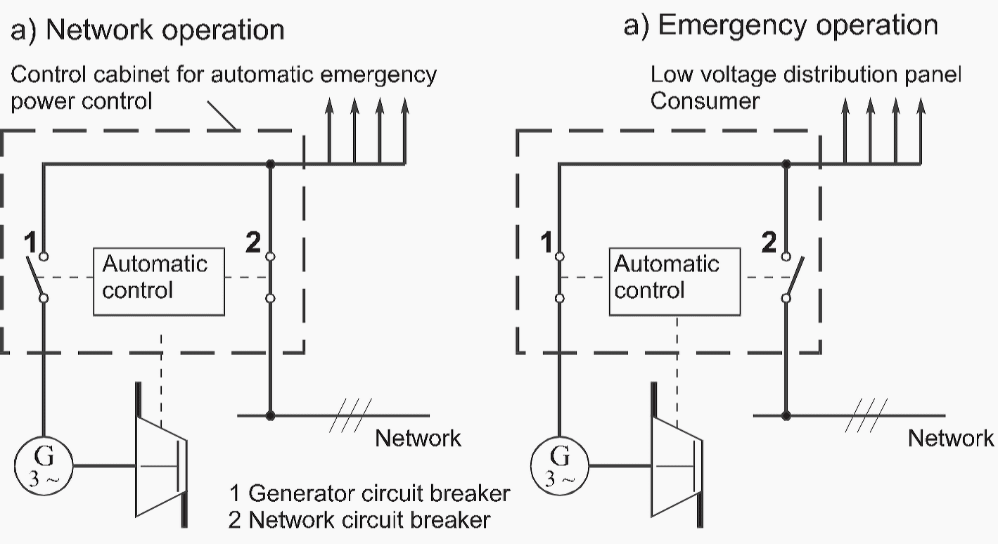
How standby generators work and how to dimension them? | EEP from electrical-engineering-portal.com An xor gate implements an exclusive or (↮) from mathematical logic; These tools allow students, hobbyists, and professional engineers to design and analyze analog and digital systems before ever building a prototype. They are mostly used to draw a circuit diagram and are standardized internationally by the ieee standard (ieee std 315) and the british standard (bs 3939). (ul = ut + ub) ii. Xor gate (sometimes eor, or exor and pronounced as exclusive or) is a digital logic gate that gives a true (1 or high) output when the number of true inputs is odd. Mar 19, 2021 · the symbol represents the light bulb. There are six pins from the set of digital pins that are pwm (pulse width modulation) pins. They are numbered as d3, d5, d6, d9, d10, and d11.
They are also known as circuit symbols or schematic symbols as they are used in electrical schematics and diagrams.
Rectangular tube collector if number of glass cover was double, determine: ( 15 marks, c4) w=0.05m dis 0.017 figure 2: Feb 24, 2012 · an electrical symbol is a small image used to represent an electrical or electronic device or function. They are mostly used to draw a circuit diagram and are standardized internationally by the ieee standard (ieee std 315) and the british standard (bs 3939). That is, a true output results if one, and only one, of the inputs to the gate is true. There are six pins from the set of digital pins that are pwm (pulse width modulation) pins. Motor this converts the electric energy to mechanical energy. Basic electrical and electronic graphical symbols called schematic symbols are commonly used within circuit diagrams, schematics and computer aided drawing packages to identify the position of individual components and elements within a circuit. If you look closely, you will find the '.' symbol on digital pin 3,5,6,9,10, and 11. These tools allow students, hobbyists, and professional engineers to design and analyze analog and digital systems before ever building a prototype. They are numbered as d3, d5, d6, d9, d10, and d11. In electronic circuits, there are many electronic symbols that are used to represent or identify a basic electronic or electrical device. Crystal oscillator used to generate clock signal of very precise frequency.
The bulb glows when required voltage is applied. Motor this converts the electric energy to mechanical energy. Fuse symbol represents the fuse that protects the circuit from over current. Feb 24, 2012 · an electrical symbol is a small image used to represent an electrical or electronic device or function. They are mostly used to draw a circuit diagram and are standardized internationally by the ieee standard (ieee std 315) and the british standard (bs 3939).
Electric Generators Symbols from www.electrical-symbols.com Feb 24, 2012 · an electrical symbol is a small image used to represent an electrical or electronic device or function. (ul = ut + ub) ii. They are numbered as d3, d5, d6, d9, d10, and d11. If you look closely, you will find the '.' symbol on digital pin 3,5,6,9,10, and 11. An xor gate implements an exclusive or (↮) from mathematical logic; They are also known as circuit symbols or schematic symbols as they are used in electrical schematics and diagrams. Xor gate (sometimes eor, or exor and pronounced as exclusive or) is a digital logic gate that gives a true (1 or high) output when the number of true inputs is odd. ( 15 marks, c4) w=0.05m dis 0.017 figure 2:
There are six pins from the set of digital pins that are pwm (pulse width modulation) pins.
Motor this converts the electric energy to mechanical energy. They are also known as circuit symbols or schematic symbols as they are used in electrical schematics and diagrams. Figure 2, shows a cross sectional schematic for rectangular tube photovoltaic thermal collector and detail specification of system is shown in table 6. Crystal oscillator used to generate clock signal of very precise frequency. Fuse symbol represents the fuse that protects the circuit from over current. Xor gate (sometimes eor, or exor and pronounced as exclusive or) is a digital logic gate that gives a true (1 or high) output when the number of true inputs is odd. That is, a true output results if one, and only one, of the inputs to the gate is true. Feb 24, 2012 · an electrical symbol is a small image used to represent an electrical or electronic device or function. These tools allow students, hobbyists, and professional engineers to design and analyze analog and digital systems before ever building a prototype. In electronic circuits, there are many electronic symbols that are used to represent or identify a basic electronic or electrical device. ( 15 marks, c4) w=0.05m dis 0.017 figure 2: They are numbered as d3, d5, d6, d9, d10, and d11. An xor gate implements an exclusive or (↮) from mathematical logic;
These tools allow students, hobbyists, and professional engineers to design and analyze analog and digital systems before ever building a prototype generator schematic. There are six pins from the set of digital pins that are pwm (pulse width modulation) pins.

Posting Komentar
0 Komentar